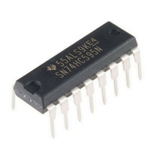
8Bit Shift Registers 3 State Output - SN74HC595N / 74HC595N / 74HC595 DIP16
- Brand: Analog Devices
- Product Code: OCP1S560119
- Availability: 100
-
₱20.00
SN74HC595N is an integrated circuit (IC) from the 74HC (High-Speed CMOS) logic family, which is manufactured by various semiconductor companies, including Texas Instruments. This specific IC is an 8-bit serial-in, serial or parallel-out shift register with an internal storage register and three-state outputs.
Key Features of SN74HC595N:
* 8-bit Shift Register: The IC can shift 8 bits of data in a serial fashion (one bit at a time) and output them either serially or in parallel.
* Serial Input (SER): Data is fed into the IC through the serial input pin.
* Parallel Output (Q0-Q7): The 8-bit data can be outputted in parallel through the eight output pins.
* Storage Register: Includes an internal register to hold data temporarily before it is transferred to the output.
* Three-State Outputs: The output pins can be in one of three states: high, low, or high-impedance (off). This feature allows multiple ICs to share the same output lines without interference.
* High-Speed CMOS Technology: Provides high-speed operation with low power consumption.
* Latch Enable (LE): This pin controls when the data in the shift register is transferred to the output register.
* Output Enable (OE): Controls whether the output pins are active or in a high-impedance state.
Pin Configuration:
The SN74HC595N typically comes in a 16-pin DIP (Dual In-line Package). Here is the standard pin configuration:
* Pin 1 (Q1): Parallel output bit 1
* Pin 2 (Q2): Parallel output bit 2
* Pin 3 (Q3): Parallel output bit 3
* Pin 4 (Q4): Parallel output bit 4
* Pin 5 (Q5): Parallel output bit 5
* Pin 6 (Q6): Parallel output bit 6
* Pin 7 (Q7): Parallel output bit 7
* Pin 8 (GND): Ground
* Pin 9 (Q7'): Serial output bit 7 (can be used to chain multiple 595 ICs)
* Pin 10 (MR): Master Reset (active low, resets all data)
* Pin 11 (SH_CP): Shift register clock input
* Pin 12 (ST_CP): Storage register clock input (latch enable)
* Pin 13 (OE): Output enable (active low)
* Pin 14 (DS): Serial data input
* Pin 15 (Q0): Parallel output bit 0
* Pin 16 (VCC): Supply voltage
Typical Applications:
* LED Displays: Controlling large arrays of LEDs with fewer microcontroller pins.
* Digital Clocks: Managing display segments for timekeeping devices.
* Data Storage: Temporarily storing and shifting data in various electronic devices.
* Signal Extension: Extending the number of outputs from a microcontroller or other digital circuits.
Operation:
* Serial Data Input (DS): Data is fed into the IC one bit at a time.
* Shift Register Clock (SH_CP): With each clock pulse, the data is shifted one position in the register.
* Storage Register Clock (ST_CP): When this clock pulse is received, the data in the shift register is transferred to the output register.
* Output Enable (OE): When low, the parallel output pins are active; when high, they are in a high-impedance state.


